


Hey guys
So a little while ago I figured I'd try and track down a bayonet lug for my Tavor, just because I can kinda deal.
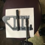
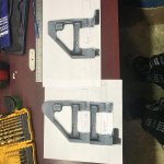
I found a couple different options such as a clamp on bayonet lug, which seems kinda flimsy to me and is bulky for what it is.
2nd is a stand alone pin on bayonet lug which would certainly be exactly what I was looking for but then in donned on me.... this could be so so much better and solve several "issues" at once...
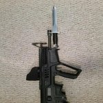
I got the Gearhead works short razor back rail on my Tavor and its great but it leaves me with no way to mount a front sight short of buying the Gearhead works flip-up front sight which is not being made anymore and seems to be impossible to find.
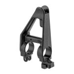
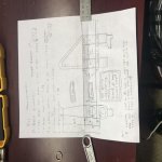
So my idea here is to have a AR15 front sight base, 3d printed with metal (the 2 bayonet lugs mentioned above are 3d printed with metal), to be tall enough as to be able to match up with any standard AR15 rear back up sight, delete the sling swivel mount on the rear mounting loop of the sight base and replace it with the bayonet lug, leaving the front mounting loop blank. this will ensure the lug is far enough back to allow the bayonet to be mounted on the 18".5 inch barrel, while simultaneously scratching my AR itch and providing me with my front sight. (This would be a pin on style as well, on both mounting loops)
So my questions here are as follows, and please, if you don't like the idea or think its stupid please just move on and keep it to yourself as its not productive to this discussion. I realize that it is a "pointless" endeavor but as I mentioned above it started as a " just because i can" or "why not" kinda thing.
So again my questions are:
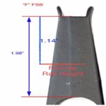
How would I take an ACCURATE measure from the top of my barrel to the focal point of the rear backup sight in order to ensure the front sight is at the same height as the rear sight? I am not sure where they should line up IE at the flat bottom of the sight post, middle, top exc. Please understand that the rear sight I will be going for will be fully adjustable (not sure if my 3d printed front sight would be adjustable for elevation, I'm thinking a fixed post and find a rear sight that is adjustable for windage and elevation to keep production as simple as possible) but if the front sight height isn't close enough to almost be perfect this wont really be worth doing. I had thought of just using a tape measure and kinda eyeballing to with the rear sight but again I don't feel this would be accurate enough.
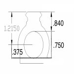
Next does somebody have a cad file, or know where to get one, so I would have something to start with and modify it as noted before by moving the bayonet lug and making it taller?
And lastly, as I have zero knowledge of this 3d drawing software (that said if nobody cant help Ill give it a go myself, just will take 5x as long) is there anybody on here able and willing to give me a hand is drawing/designing this part in a 3d printer friendly program?
Thanks guys and take care!
Here’s a concept photo by daver_II

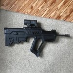
And I’ll attach my rifle to show my rail height being higher than standard thus needing a higher front sight than the prior pictured rifle

So a little while ago I figured I'd try and track down a bayonet lug for my Tavor, just because I can kinda deal.
I found a couple different options such as a clamp on bayonet lug, which seems kinda flimsy to me and is bulky for what it is.
2nd is a stand alone pin on bayonet lug which would certainly be exactly what I was looking for but then in donned on me.... this could be so so much better and solve several "issues" at once...
I got the Gearhead works short razor back rail on my Tavor and its great but it leaves me with no way to mount a front sight short of buying the Gearhead works flip-up front sight which is not being made anymore and seems to be impossible to find.
So my idea here is to have a AR15 front sight base, 3d printed with metal (the 2 bayonet lugs mentioned above are 3d printed with metal), to be tall enough as to be able to match up with any standard AR15 rear back up sight, delete the sling swivel mount on the rear mounting loop of the sight base and replace it with the bayonet lug, leaving the front mounting loop blank. this will ensure the lug is far enough back to allow the bayonet to be mounted on the 18".5 inch barrel, while simultaneously scratching my AR itch and providing me with my front sight. (This would be a pin on style as well, on both mounting loops)
So my questions here are as follows, and please, if you don't like the idea or think its stupid please just move on and keep it to yourself as its not productive to this discussion. I realize that it is a "pointless" endeavor but as I mentioned above it started as a " just because i can" or "why not" kinda thing.
So again my questions are:
How would I take an ACCURATE measure from the top of my barrel to the focal point of the rear backup sight in order to ensure the front sight is at the same height as the rear sight? I am not sure where they should line up IE at the flat bottom of the sight post, middle, top exc. Please understand that the rear sight I will be going for will be fully adjustable (not sure if my 3d printed front sight would be adjustable for elevation, I'm thinking a fixed post and find a rear sight that is adjustable for windage and elevation to keep production as simple as possible) but if the front sight height isn't close enough to almost be perfect this wont really be worth doing. I had thought of just using a tape measure and kinda eyeballing to with the rear sight but again I don't feel this would be accurate enough.
Next does somebody have a cad file, or know where to get one, so I would have something to start with and modify it as noted before by moving the bayonet lug and making it taller?
And lastly, as I have zero knowledge of this 3d drawing software (that said if nobody cant help Ill give it a go myself, just will take 5x as long) is there anybody on here able and willing to give me a hand is drawing/designing this part in a 3d printer friendly program?
Thanks guys and take care!
Here’s a concept photo by daver_II
And I’ll attach my rifle to show my rail height being higher than standard thus needing a higher front sight than the prior pictured rifle
Attachments
Last edited: