











































Tang Sight

mooncoon

CGN Ultra frequent flyer
Rating - 100%
22   0   0
Location
Vancouver Island
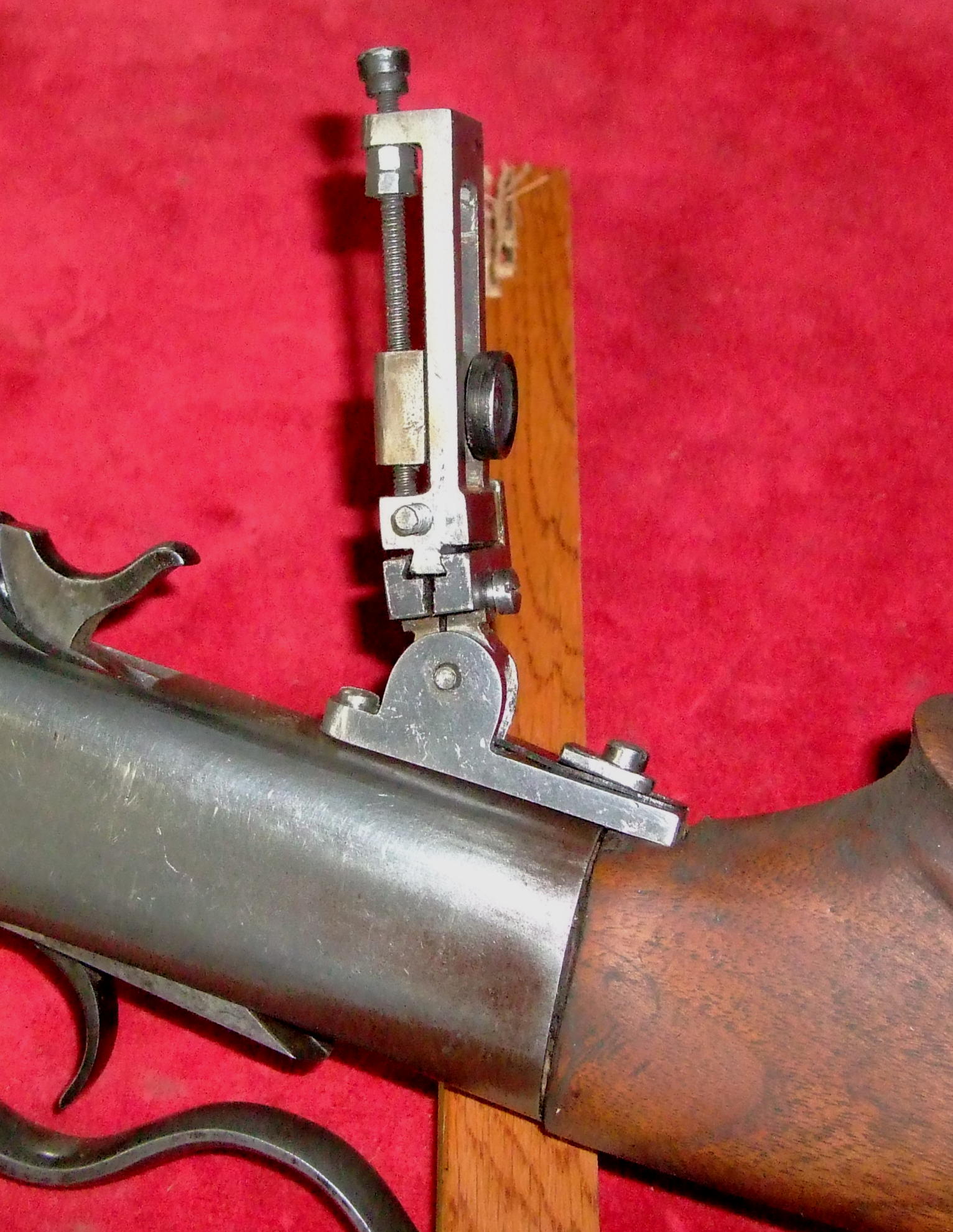
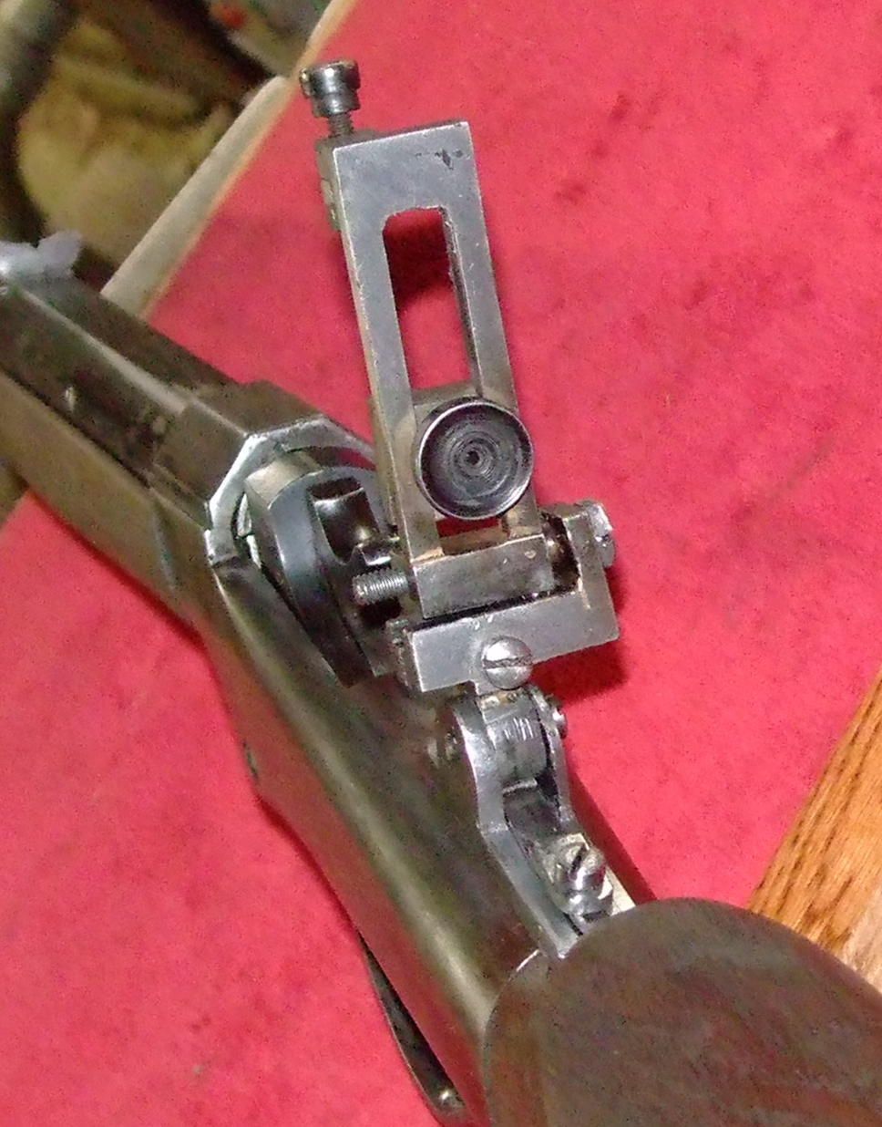
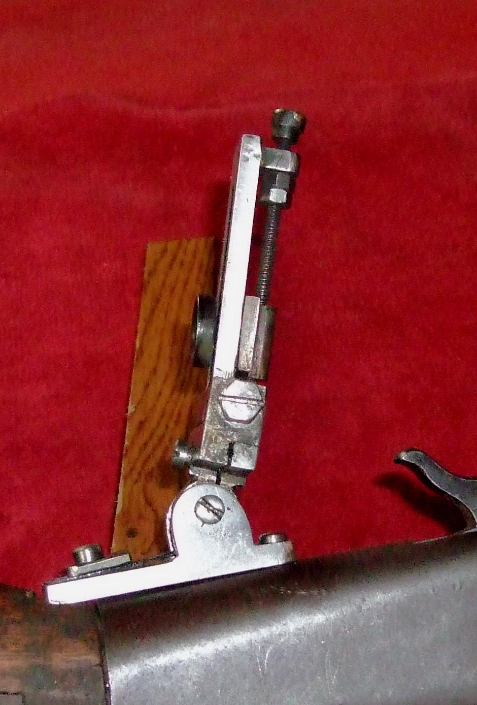
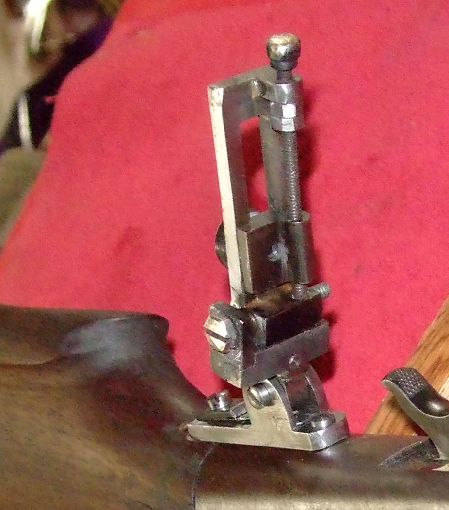
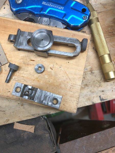
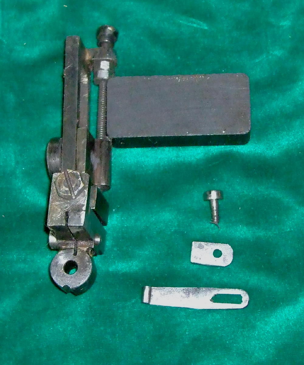
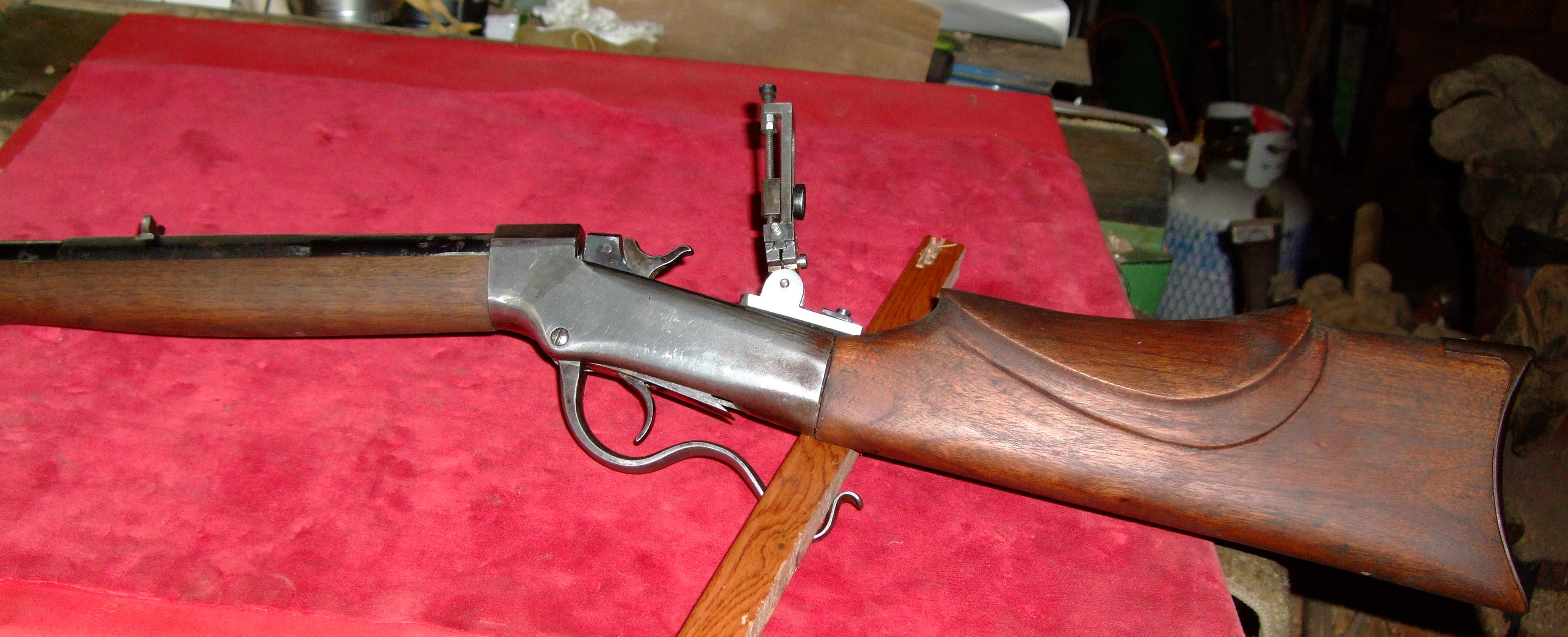
Thought I would post some pictures of my newest project. I was given a Ballard receiver, recently and in part that meant that I needed a tang sight for it. Being frugal ( some might say cheap) I decided to copy a manufactured one on one of my other guns. First thing that comes to mind is that making a tang sight is a remarkable amount of work but while far from being as well made as the one I copied, it does work. For those inclined to make one of their own, one detail that I had not thought about much before is that by making the pivot portion quite tall, it takes a lot of side to side slop out of the mast. In the past I had only considered making the base screw that the sight pivots on, longer and a closer fit, but making the sides of the base taller and the pivot portion larger in diameter is much easier and much more effective. What might not be too obvious is that I silver soldered a number of pieces together which saved a lot of difficult machining

cheers mooncoon
vzY6tPZ.jpg


TLKF7dY.jpg


whUgvfH.jpg


GCdKmg4.jpg


vydu7Q8.jpg
 
Last edited:
Nice work!

I like your lock setup. On the ones I've built I've tried a few different things, I like the spring loaded ball the best and just thumbscrew to tighten; but might have to borrow your idea there for the next one. I was going to use a piece of flat spring with an "L" underneath (as with a factory sight I have) but trying to get it to work was proving more frustrating than the ball & spring.

For my part, locating the detent notch hasn't been too difficult; I ensure the eyepiece is level with the "sighting plane" and carefully mark everything externally, with at least a couple of reference points. Then hope I measured right :)

I appreciate using the dovetail setup for the windage and can see why it's the preferred method. I made a "carrier" for mine for the windage, which results in the staff being kinda bulky with the adjuster screw and a lock knob; I like the look on some rifles but the dovetail method is pretty simple and less likely to move on ya as well. You can't see it in that photo, maybe I'll pull it outta the safe:

tfGv9oB.jpg
 
Last edited:
re the locating of the detente notch etc; I filed a half round notch in the bottom of the base piece and use a sliding spring to locate the correct position. Ie there is an L shaped spring that pushes up into the notch and instead of a single screw hole in the other end of the spring, there is a slot. With the spring loose, I raise the mast until I get the brightest view through the peep sight and then tighten the screw that holds the spring in place. Saves an awfully lot of worry and fiddling. The L shaped detente spring is partially forged out of 1/4" drill rod then ground and filed to shape. I think the main body of the spring is about 35 thousandths thick and ends with a rounded bump on the end (that goes in the notch ). To temper the spring, I heat it red hot then water quench and draw the temper in molten lead between 720 F and 740 F for 3 minutes by the clock. 3 minutes seems forever when you are watching the clock. On thing that I did that in hind sight was an improvement; The screw holding the spring in place is a 4 x 36 tpi and when I tried to thread it right to the head of the screw, it snapped off. I stopped the threads on the second screw about 40 or 50 thou short and made an elongate washer to cover the unthreaded portion. What was good about that was that it covered the entire slot in the spring so that I was not left with a very thin section of spring. Also I save the small remnants of the cutting discs for my Dremel tool and used one of them to cut the slot in the spring ( and cleaned that up with a needle file )

cheers mooncoon
 
Making springs is certainly an art on its own, I need a lot more practice in that department. Some of mine work, some don't, but that's what practice is all about.

I've noticed those really small (#4-#6) screws can do some unexpected things, as can the taps if things aren't perfect.
 
Making springs is certainly an art on its own, I need a lot more practice in that department. Some of mine work, some don't, but that's what practice is all about.
.

I use drill rod to make my springs because it is very repeatable. I draw the temper in molten lead because that gives a very uniform heat with no local hot or cold spots and I also have and use a high temperature thermometer that cost $25 or $30 from Brownells, at least 30 years ago. That allows me to be sure of what temperature the lead is. Before the thermometer I floated a thin piece of bright iron or steel on the lead and when the colour went from blue black to grey, pulled the plug out. I think the thermometer was well worth the cost. Most main springs, in my experience, taper from .1" at the bend or at the thickest portion, to about .70" at the slender end and the biggest guess work is deciding how much pre-load to put on the spring. Pre-load is the amount the spring has to be compressed or bent before it reaches the location where it will be in its released position (as opposed to at full ####).

cheers mooncoon
 
I use drill rod to make my springs because it is very repeatable. I draw the temper in molten lead because that gives a very uniform heat with no local hot or cold spots and I also have and use a high temperature thermometer that cost $25 or $30 from Brownells, at least 30 years ago. That allows me to be sure of what temperature the lead is. Before the thermometer I floated a thin piece of bright iron or steel on the lead and when the colour went from blue black to grey, pulled the plug out. I think the thermometer was well worth the cost. Most main springs, in my experience, taper from .1" at the bend or at the thickest portion, to about .70" at the slender end and the biggest guess work is deciding how much pre-load to put on the spring. Pre-load is the amount the spring has to be compressed or bent before it reaches the location where it will be in its released position (as opposed to at full ####).

cheers mooncoon

Thanks; I've followed some of your other threads (few years ago I think) on spring making. Good advice!

Re: Making tang sights generally, one of the reasons I like it is that the generic tang sights don't always "fit" the look and style of the rifle. Particularly so on smaller frame rifles, in my opinion. The bases are always tricky, not in the mechanical sense necessarily but in keeping that curve well-balanced aesthetically.

Yours fits that Ballard nicely, looks great. You planning on browning or rust bluing it?
 
Re: Making tang sights generally, one of the reasons I like it is that the generic tang sights don't always "fit" the look and style of the rifle. Particularly so on smaller frame rifles, in my opinion. The bases are always tricky, not in the mechanical sense necessarily but in keeping that curve well-balanced aesthetically.

Yours fits that Ballard nicely, looks great. You planning on browning or rust bluing it?

I don't think I will blue it on the short run, maybe in time. I think the hard part of making the base is hollowing it out underneath to fit the curve of the tang or back of the receiver. I should have hollowed this base out more but it is vertical and stable and I don't want to change it, I took a photo of the spring that centers the mast vertical, to give you a better idea of what it looks like. The advantage of the slotted spring is that it can be easily adjusted for different angles of tangs. As mentioned before, the advantage of the type of base and pivot that I copied is that it minimizes the amount of sideways slop and by tightening the pivot screw up, I can eliminate the side to side wobble. I think I might end up making another one or two of these sights to fit some of my other rifles and as you noted, I can vary the width of the base to suit the tang that it is going on to

cheers mooncoon

gYBJZ70.jpg
 
Yes those bases do get VERY thin towards the finish line. Easy to take one pass too many, I have a couple lying on my bench to remind me. That's a big reason those bases sort of have to be raised a little. Gets more challenging because the bottom side needs to be concave.

Mine also take up the slop nicely with a smart turn on the knurled pivot.
 
I have messed with a few scope bases to fit the curvature of tangs and found if I wanted the curve to match the tang, the best way was to re-create the tang dimensions with a piece of round stock or heavy wall pipe. Drill holes in the sight base & corresponding holes in the form. Now place a couple pins in the holes of the form and place sight base over them, now press the sight base with hyd press onto the form until it molds itself. This works for a formable flat bar base but would be hard to replicate with a milled base such as yours.

With a milled base such as yours I make the base form such as you have and drill the holes so square with the tang then I just mill a straight ,flat slot into the underside of the base. Now I take a large crescent shaped fine file and break the edges on the slot sides. It doesn't take much filing and the curvature your creating doesn't have to match the tang exactly. Just make sure you don't file enough that the underside of the slot at the screw holes doesn't come in contact with the tang. The sight base will anchor down both sides and is easily centered and made upright square with your tang. It works very well and is a he11 of a lot easier than trying to anchor a base upright and cut a matching curve with a big fly-cutter.
 
I have messed with a few scope bases to fit the curvature of tangs and found if I wanted the curve to match the tang, the best way was to re-create the tang dimensions with a piece of round stock or heavy wall pipe. Drill holes in the sight base & corresponding holes in the form. Now place a couple pins in the holes of the form and place sight base over them, now press the sight base with hyd press onto the form until it molds itself. This works for a formable flat bar base but would be hard to replicate with a milled base such as yours.

With a milled base such as yours I make the base form such as you have and drill the holes so square with the tang then I just mill a straight ,flat slot into the underside of the base. Now I take a large crescent shaped fine file and break the edges on the slot sides. It doesn't take much filing and the curvature your creating doesn't have to match the tang exactly. Just make sure you don't file enough that the underside of the slot at the screw holes doesn't come in contact with the tang. The sight base will anchor down both sides and is easily centered and made upright square with your tang. It works very well and is a he11 of a lot easier than trying to anchor a base upright and cut a matching curve with a big fly-cutter.

Yup, I use a ball end mill and a half round to get the underside where I want in that respect. And yes. the whole thing ends up very thin by the time you're done. As I say above, it's all too easy to get greedy and go too far at that point. My comment around "curves" above is more aimed at the aesthetics of the overall base; and getting the pivot "hump" to "look right" in relation to everything else. It's all very subjective (and personal taste to a certain extent) at that point.
 
having never used a ball end mill, I am thinking it would not be hard to make a small slitting saw with the cutting edge curved to approximately match the curve of the tang or receiver. The blade would not have to be large diameter ; 5/8 or 3/4" would probably work

cheers mooncoon
 
having never used a ball end mill, I am thinking it would not be hard to make a small slitting saw with the cutting edge curved to approximately match the curve of the tang or receiver. The blade would not have to be large diameter ; 5/8 or 3/4" would probably work

cheers mooncoon

I could see that working very well. I'd have to look but I believe my ball endmill is 3/4" and exactly right, it doesn't have to go deep - Just enough to make it settle down on the curve a little.
 
I could see that working very well. I'd have to look but I believe my ball endmill is 3/4" and exactly right, it doesn't have to go deep - Just enough to make it settle down on the curve a little.

I think the merit of a slitting saw design is that you could make it with a very large curve radius. The Ballard for example probably has a radius of 2 or 3" . As long as you took shallow cuts, you could probably soft solder the base to lay on its side on a piece of angle iron or alternately if you created the base hollow first, use small bolts through the waste material which you would be removing next. Just to be clear; a 3/4" diameter cutter with a shallow curve across it (in the vertical axis) and cutting on its side with the sight base laying on its side

cheers mooncoon
 
I think the merit of a slitting saw design is that you could make it with a very large curve radius. The Ballard for example probably has a radius of 2 or 3" . As long as you took shallow cuts, you could probably soft solder the base to lay on its side on a piece of angle iron or alternately if you created the base hollow first, use small bolts through the waste material which you would be removing next. Just to be clear; a 3/4" diameter cutter with a shallow curve across it (in the vertical axis) and cutting on its side with the sight base laying on its side

cheers mooncoon

Seems like a good idea; I can visualize what you are saying. One spends as much if not more time making fixtures, jigs and cutting tools, as one spends on the project itself. :)
 
Seems like a good idea; I can visualize what you are saying. One spends as much if not more time making fixtures, jigs and cutting tools, as one spends on the project itself. :)

Oh wow 10-4 on the jig making, My jig making time to actual "piece" time is easy 3:1.

another option that would be quicker (but certainly more costly) over a slotting blade, would be a large dia woodruff cutter used cross-cut wise. costly but you would have a cutter that would do a lot of sight base's.
 
Oh wow 10-4 on the jig making, My jig making time to actual "piece" time is easy 3:1.

another option that would be quicker (but certainly more costly) over a slotting blade, would be a large dia woodruff cutter used cross-cut wise. costly but you would have a cutter that would do a lot of sight base's.

Oh good idea, worth trying. I think I have one or two here I just hadn't thought of trying them like that. See if I can find some time here over the next couple of weeks, I have another couple to make soon and I have some bases roughed in.
 
Oh wow 10-4 on the jig making, My jig making time to actual "piece" time is easy 3:1.

another option that would be quicker (but certainly more costly) over a slotting blade, would be a large dia woodruff cutter used cross-cut wise. costly but you would have a cutter that would do a lot of sight base's.

I think what I am suggesting is a home made woodruff cutter and woodruff cutters are a form of slotting saw. I think I can probably make a suitable cutter in an hour roughly. The cutting portion does not have to be large diameter and 3/4" diameter should be quite adequate and it is the radius of the curve that is important. I would file the curve onto the cutter before cutting a filing the teeth. Essentially turn a 3/4" cutting head then a 1/2" stem above that and file a curve across the head and cut teeth into it with a hacksaw and file. I would heat it red hot and quench spinning to avoid warping and finally draw to dark brown.

cheers mooncoon
 
Im sure what your doing works for you and I must be not grasping something here...cant visualize how a 3/4 dia cutter would mirror a curve form that the 2" dia wrist has...I'm back to thinking a plain ol' 3/8 endmill cut, square sided, flat bottom groove in the sight base and then break the trough edges with half round could be done in 1/2 the time to make a cutter.
 
Im sure what your doing works for you and I must be not grasping something here...cant visualize how a 3/4 dia cutter would mirror a curve form that the 2" dia wrist has...I'm back to thinking a plain ol' 3/8 endmill cut, square sided, flat bottom groove in the sight base and then break the trough edges with half round could be done in 1/2 the time to make a cutter.

Lets start with a Woodruff cutter mounted vertically and cutting on its side ; if you move a piece of metal past it, in a horizontal direction, the cutter will cut a flat vertical surface. If the Woodruff cutter instead of having flat teeth has teeth that are curved top to bottom, in a U shape with the largest diameter of the cutter in the middle, it will cut a curved hollow in the work.

if the sight base is laying on its side and fasted to a piece of angle iron, the bottom of the base can be moved past the cutter and have a hollow channel milled into its bottom. Think of the cutter as being an upside down T where the head of the T is the actual cutting portion. The thickness of the head (the top of the T) needs to be greater than the width of the sight base but the diameter of the T is unimportant in practical terms because it is the curve top to bottom which is important. I will try to get around to making one in the next few days and post a photo of it

cheers mooncoon
 
Back
Top Bottom